

 English
 Español
 Deutsch
 中文简体
中文简体
Product Consultation
Your email address will not be published. Required fields are marked *
Content
A three-phase feeder can carry hundreds of amps, and the meter measuring it should never become part of the load. That is the simple idea behind a 3 phase ct operated energy meter: current transformers step the line current down to a small secondary signal, usually 1 A or 5 A, and the meter measures that instead of the full current. It sounds like a minor detail until you are standing in front of 400 A busbars with no space for a direct-connection device. Over the years we at Eastron have supplied CT operated meters into factories, charging depots, rooftop solar installations and data halls, and the questions raised during selection are almost always the same. This guide walks through them in the order they usually appear.
A CT operated three-phase meter is designed to accept the secondary output of external current transformers rather than the primary load current. The main conductors pass through, or are terminated into, the CTs; the meter only sees a proportionally reduced current, while its voltage inputs connect directly to the three phases and, in a 3P4W system, the neutral. The meter therefore needs two things to display meaningful values: the correct system configuration, and the CT ratio entered into its setup so that secondary amps are converted back into primary amps for display and for the energy registers.
Because the heavy current stays outside the instrument, the meter itself can remain compact. Many DIN rail units measure three phases in a 72 mm wide enclosure, and panel-mounted versions drop into standard 96 x 96 mm cut-outs. Beyond kWh, a modern CT operated meter typically reports voltage, current per phase, power factor, frequency, active and reactive power, demand, and in some models total harmonic distortion. Bidirectional versions separate imported from exported energy, which matters as soon as rooftop PV or a battery is connected on the same site.
Direct connected meters are simpler and cheaper, and for small distribution boards and light sub-metering they are usually the better answer. The crossover point tends to sit around 80 to 100 A per phase, but current is only one consideration. If the cable is too large for the meter terminals, if the feeder cannot be shut down for long, or if the installation has to be metered without cutting conductors at all, CT operated metering is the practical route.
| Consideration | Direct connected | CT operated |
|---|---|---|
| Maximum load current | Typically up to 80 to 100 A | Limited only by the CT primary rating |
| Current at meter terminals | Full load current | 1 A or 5 A secondary |
| Cable size accepted | Small, terminal-sized conductors | Any size that fits the CT window |
| Retrofit to existing feeders | Needs isolation and re-termination | Split-core CTs clamp on without cutting |
| Typical applications | Small boards, tenancy sub-metering | Main incomers, plant, EV charging, PV |
| Cost profile | Lower upfront cost | Meter plus CTs, more flexible long term |
Two meters with the same feature list can behave very differently on site, and the difference usually comes from three specification lines: the CT ratio, the accuracy class, and the burden.
Choose a CT primary rating at or just above the maximum expected load current, with modest headroom: 100, 200, 250, 400, 600 and 1000 A are the common steps. Headroom matters because CTs are most accurate between roughly 20% and 120% of rated current. A CT that is far oversized for a lightly loaded feeder will read poorly at low load. On the secondary side, 5 A is the traditional standard, while 1 A is preferable on long cable runs because it carries a much lower burden and allows thinner connecting cable. Low-level outputs, such as the mV or mA signals from three-in-one sensors and Rogowski coils, follow the same logic with an even smaller signal.
System accuracy is a chain, not a single number. A Class 1 meter paired with a Class 1 CT will not deliver Class 1 system accuracy. Where readings are used for billing, Class 0.5S meters with Class 0.5 or 0.5S CTs are the usual expectation. Burden is the other half of the story: the total volt-amperes of the meter current circuit plus the connecting cable must stay within the CT rated burden. Long runs of 2.5 mm² cable on a 5 A secondary can exhaust that budget quickly, which is exactly why 1 A secondaries are chosen for distant panels or for meters sharing a single CT set.
Decide early whether you need simple energy registration or a multifunction instrument. Multi-tariff registers, demand logging, import and export measurement, power quality parameters, digital inputs and relay outputs for load control all change the model you order, and adding them later means replacing hardware.
CT metering is safe and reliable when a few rules are respected during installation and maintenance. Most field problems trace back to one of these points.
RS485 with Modbus RTU remains the workhorse for CT operated meters, because it daisy-chains well and is understood by nearly every building management and SCADA platform. M-Bus is common where utility-style reading or tenancy billing is involved. Ethernet with Modbus TCP suits data centres and other sites that already run an IP backbone across rows of cabinets. Wi-Fi and LoRaWAN help on rooftops and remote plant rooms where pulling cable is expensive, while a simple pulse output still serves installations that only need a remote counter to follow the meter. When the meter's native port does not match the network, a DIN rail protocol converter or serial server bridges RS485 to Ethernet, Wi-Fi or cellular, and the register map in our download centre tells you exactly which values can be polled.
For any installation where the reading ends up on an invoice, certification is part of the specification rather than an afterthought. MID approval is the reference point in the European Union for legally relevant metering, UL and ETL listings cover North American projects, and PTB with Eichrecht approval addresses German requirements for charging point billing. It is worth remembering that approval applies to a measurement chain: the CTs used with a certified meter may need their own documentation, especially where current transformers are part of the billed path. A DIN rail, RS485 Modbus CT operated MID energy meter is a common building block for these projects.
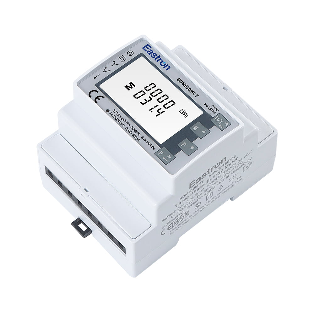 RS485 Modbus CT operated Din Rail Three Phase MID Energy MeterWork with 3P4W/3P3W/1P2WView Product →
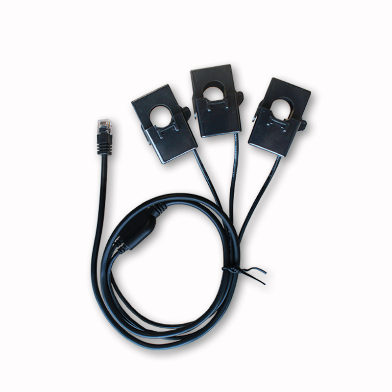
The meter is only half of the measurement. Split-core CTs are the practical choice for retrofits because they clamp around existing conductors without disconnection, while solid-core models are preferred in new builds where higher accuracy and mechanical stability matter. Three-in-one CTs combine all three phases in one housing and cut wiring time considerably, particularly in compact DIN rail cabinets where space above the meter is limited. Flexible Rogowski coils, paired with an integrator, handle very large or awkwardly shaped busbars and are often chosen for power quality work. Whichever family you pick, check the window size, the accuracy class, the secondary type and the rated burden against the meter input before ordering.
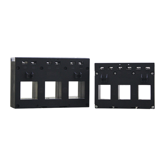 5A output 3-in-1 Current Sensor (CT)3-in-1 Current TransformerView Product →
Working through these points in order keeps most projects out of trouble and gives suppliers everything they need to quote accurately.
A three-phase, RS485 Modbus, CT type multifunction energy meter covers the majority of industrial and commercial requirements and is the usual starting point for comparison.
 CT Type Three Phase RS485 Modbus Multi-function Energy MeterMulti-parameter measurementsView Product →
CT operated metering rewards a little planning. Once the ratio, class, burden and communication path line up, the installation tends to run quietly for years, producing data that finance, operations and maintenance teams can all rely on. If you are still weighing options, our engineering team is happy to review a single-line diagram and suggest a configuration; the background of how we build and support these products is on our about page, and the article on why three-phase MID metering matters for billing explains the compliance side in more depth.
Your email address will not be published. Required fields are marked *

We develop and produce high performance electricity meters, power analyzers, current sensors, communication modules and management systems.
Address:NO. 52, Dongjin Road, Nanhu, Jiaxing, Zhejiang, China
Copyright @ Eastron Electronic Co., Ltd. All rights reserved
