

 English
 Español
 Deutsch
 中文简体

Product Consultation
Your email address will not be published. Required fields are marked *
Content
A 3 phase kWh meter with CT is more than a larger energy meter. It is a measuring system made of current transformers, a meter designed for 1 A or 5 A inputs, and the wiring that connects them. When those parts are matched properly, the meter can measure large three-phase loads without carrying the full service current through its terminals. That is why CT-operated meters are common in commercial buildings, industrial panels, solar installations, EV charging, and tenant metering.
In our work with panel builders and energy teams, the questions are usually practical: which CT ratio should we use, what accuracy class matters, how do we wire polarity, and how do we get reliable data out of the meter? This guide walks through those decisions in the order they tend to appear on a real project.
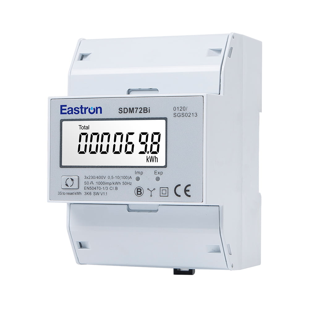
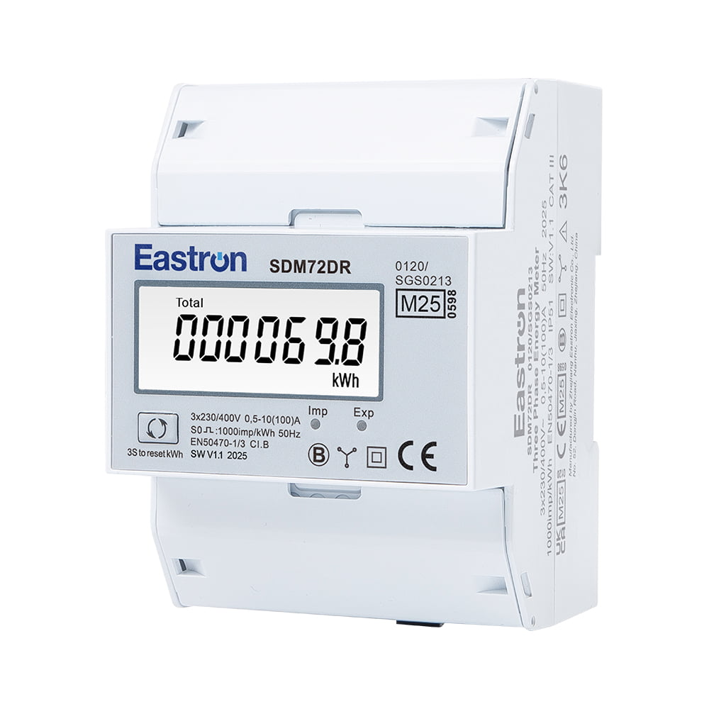
 Eastron SEM3-M Three-Phase CT Energy Meter with ModbusA DIN-rail CT-operated three-phase meter with RS485 Modbus, useful as a reference for sub-metering and monitoring projects.View Product →
A DIN-rail, CT-operated three-phase meter with RS485 Modbus is a good reference point for many monitoring and sub-metering projects. It shows the basic pattern: external CTs reduce the current, the meter measures voltage and secondary current, and the controller or gateway reads the result over a serial bus.
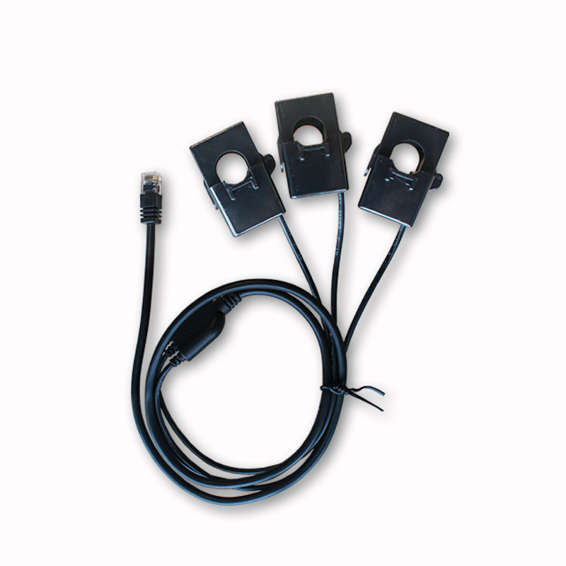
The CTs sit around the phase conductors and produce a secondary current proportional to the primary current. A 200/5 CT, for example, turns 200 A in the primary into 5 A in the secondary. The meter does not measure 200 A directly. It measures the 5 A secondary signal and applies the programmed ratio to calculate primary current and energy.
This arrangement keeps the meter compact and keeps high current away from its terminals. It also means the accuracy of the reading depends on more than the meter alone. The CT ratio, CT class, burden, cable length, terminal tightness, and polarity all sit in the same measurement chain. A high-accuracy meter connected to an unsuitable CT will still produce an unsuitable result.
CT-operated meters are often confused with direct-connected meters. A direct meter carries the full load current through its own terminals, which is convenient for smaller services. A CT meter is the better choice when the service is large, when cable routing makes direct connection impractical, or when the panel design calls for separate current transformers. The two approaches solve different problems, and the selection should follow the service size and project requirements rather than habit.
Start with the maximum expected primary current. The CT primary rating should be above the normal operating current but not so far above it that the meter spends its life reading a small fraction of the CT range. A CT that is heavily oversized can make low-load accuracy less useful, especially when the site has long periods of light load. It is common to allow some headroom for future load, but the headroom should be deliberate.
The secondary rating must match the meter input. Most three-phase CT meters accept 5 A or 1 A secondary current, and the datasheet will state which. A 1 A secondary can be helpful on long cable runs because the current is lower, but the CT and meter must both be rated for it. Never assume a meter accepts both without checking the label and manual.
Accuracy class is often read as a single number, but it describes the whole meter or CT under defined conditions. A class 0.5S meter and a class 0.5 CT can form a good system, but only if the burden and wiring are also correct. For tenant billing or utility-facing measurement, check whether the project requires MID or another approval scheme, and confirm that the complete metering arrangement meets that requirement.
Most CT wiring problems are not mysterious. They come from a reversed polarity, a mismatched phase, a secondary left open, or a ratio entered incorrectly. The CT has a polarity mark, usually P1 on the primary and S1 on the secondary. The conductor should pass through the CT in the marked direction, and the S1 lead should go to the meter input that corresponds to that polarity. If the phase is reversed, the meter may show negative power or subtract energy when the load is actually consuming.
Never open a CT secondary while primary current is flowing. The secondary can develop a dangerous voltage, and the CT can be damaged. Short the secondary through a suitable shorting terminal before disconnecting the meter. Earth the secondary circuit at one point according to local practice and the project specification, and do not create multiple earth paths by accident.
The right meter depends on what the data will be used for. A simple monitoring point may need only kWh, instantaneous power, and RS485 Modbus. A billing or tenant metering point may need MID approval, multi-tariff registers, demand logging, or a specific communication protocol. A power quality study may need harmonics, THD, and waveform data, which is a different product category from a basic kWh meter.
It also helps to decide early whether the meter will be read locally or through a system. Pulse output is useful for simple energy pulses, but it does not give voltage, current, or power factor. RS485 Modbus is common for panels and building management. M-Bus is often used in utility and sub-metering environments. Ethernet and Modbus TCP suit data centers and larger networks. Wi-Fi and LoRaWAN can be useful where a wired bus is not practical, but they bring their own commissioning and network reliability questions.
| Consideration | CT-operated meter | Direct-connected meter |
|---|---|---|
| Current path | External CTs reduce current to 1 A or 5 A | Full load current passes through meter terminals |
| Typical service size | Large commercial and industrial services | Smaller single-phase and three-phase services |
| Installation | Requires CT mounting, polarity checks, and ratio setup | Simpler terminal connection for suitable loads |
| Accuracy risks | CT class, burden, ratio, polarity, and wiring | Meter class, terminal torque, and load range |
| Good fit | Panel metering, tenant billing, PV, EV, data centers | Small buildings, retail units, light industrial loads |
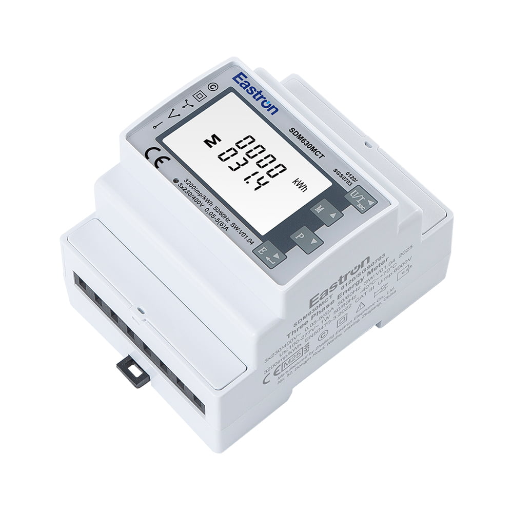 Eastron SDM630MCT MID CT-Operated Three-Phase Energy MeterA MID-certified CT-operated three-phase meter with RS485 Modbus and pulse outputs, suited to billing-related measurement where approval is required.View Product →
Where the project needs a declared approval for billing-related measurement, a MID CT-operated three-phase meter is often the more appropriate starting point than a general monitoring model. The key is to match the approval, CT ratio, and communication needs together rather than choosing each part separately.
A CT meter is only as useful as the data it delivers. For a Modbus RTU network, plan the daisy-chain layout, baud rate, parity, slave addresses, and termination before installation. Keep the bus wiring away from power cables where possible, and do not mix devices with incompatible signal arrangements on the same segment without checking the interface. For Ethernet meters, confirm IP addressing, gateway settings, and whether the platform expects Modbus TCP, MQTT through a gateway, or another data path.
Commissioning should include a comparison between the meter reading and an independent check, such as a clamp meter on the primary conductor or a known load bank. Check that the current and voltage phases agree, that power direction is correct, and that the CT ratio in the meter matches the installed CTs. If the site has solar, storage, or bidirectional flow, confirm that import and export registers behave as expected. A meter that reads correctly at full load but shows odd values at light load may have a ratio or burden issue rather than a display fault.
 Eastron SDM630MCT-TCP Three-Phase CT Energy Meter with Modbus TCPA CT-operated three-phase meter with Ethernet Modbus TCP for remote reading and programming in networked energy monitoring installations.View Product →
For networked projects, a CT-type three-phase meter with Ethernet Modbus TCP can simplify integration where a serial bus is not the natural fit. The same selection discipline still applies: CT ratio, class, burden, and phase polarity come before any communication setting.
CT-operated meters are a practical fit for main incoming panels, distribution boards, tenant sub-metering, solar PV and zero-export monitoring, EV charging infrastructure, and data center power chains. They are also useful when a panel builder wants to keep the meter footprint small while measuring a large feeder. In each case, the meter should be selected as part of a measurement chain rather than as a stand-alone item on a purchase list.
Before ordering, gather the service current, voltage, frequency, CT ratio, required accuracy class, communication protocol, and any approval requirement. Check the panel space, the CT mounting method, and whether the CT secondary is 1 A or 5 A. Then confirm the meter configuration range and the available documentation. Our download library includes datasheets, user manuals, and protocol documents that can help with this check, and you can learn more about our measurement background on the about page.
When the CT ratio, class, burden, polarity, and communication settings are treated as one design decision, a 3 phase kWh meter with CT becomes a reliable part of the electrical installation. When they are treated as separate purchases, the meter may still run, but the numbers it produces may not be the numbers the project needs.
Your email address will not be published. Required fields are marked *

We develop and produce high performance electricity meters, power analyzers, current sensors, communication modules and management systems.
Address:NO. 52, Dongjin Road, Nanhu, Jiaxing, Zhejiang, China
Copyright @ Eastron Electronic Co., Ltd. All rights reserved
