

 English
 Español
 Deutsch
 中文简体
中文简体
Product Consultation
Your email address will not be published. Required fields are marked *
Content
Three-phase supplies are rarely small. A panel feeding a factory line, a bank of DC chargers, or a rooftop PV array can carry hundreds of amps per phase, and no practical meter has terminals large enough to pass that current straight through. That is why a 3 phase energy meter with CT has become such a common answer: the current is stepped down by current transformers, and the meter measures the scaled-down secondary current instead. The meter itself becomes smaller, easier to replace, and the heavy current never touches its terminals.
What follows is a practical walk through how these meters work, which lines in a datasheet really matter, where installation usually goes wrong, and how to pick the CTs that go with them.
A CT-operated meter measures voltage directly and current indirectly. Its voltage terminals connect to L1, L2, L3 and N and see the real system voltage. Line current, by contrast, flows through the primary of a current transformer, usually the cable or busbar passing through the CT window, and the meter only ever sees the secondary output, most often 1 A or 5 A.
A CT is a simple device with a serious job. Its core surrounds the conductor, and its secondary winding produces a current proportional to the primary, scaled by the ratio: 200/5, 400/5, 1000/5 and so on. Because the meter is effectively measuring a copy of the current rather than the current itself, the accuracy of the whole installation depends on both parts. A Class 0.5S meter paired with a poor-quality CT will not deliver billing-grade results.
Two practical points follow. First, the CT secondary must match the meter input: a 5 A meter needs 5 A CTs, and a 1 A meter needs 1 A CTs. Second, the CT burden rating has to cope with the wiring loop plus the meter input, or the secondary current will be distorted and readings will drift, particularly at low load.
Beyond simple kilowatt-hours, a modern three-phase CT meter typically reports per-phase and total active power, reactive and apparent power, power factor, voltage, current, frequency and often total harmonic distortion. Many units keep separate import and export registers, support several tariff registers with time-of-use switching, and offer pulse outputs or digital inputs for simple integration with older control gear.
Communication is usually where the real decisions are made. RS485 with Modbus RTU remains the workhorse protocol, with M-Bus and DLT645 appearing where utilities or specific markets expect them. Ethernet with Modbus TCP, Wi-Fi and LoRaWAN versions exist for sites where pulling a bus cable is impractical.
Direct-connected meters are perfectly adequate for smaller three-phase loads. They are compact, need no extra components, and their 45 A or 100 A ratings cover a lot of commercial boards. Once the load climbs past that, or when the conductor is a busbar rather than a cable, CT operation becomes the only sensible option.
| Consideration | Direct connection | CT operated |
|---|---|---|
| Typical current range | Up to roughly 100 A per phase | Hundreds to thousands of amps |
| Wiring effort | Load cable lands on meter terminals | Conductor passes through the CT; only secondary wiring reaches the meter |
| Safety at the meter | Full load current present at the terminals | Only a fraction of the primary current present |
| Flexibility | Limited by terminal size | Range set by CT ratio; meter can be swapped without cutting the busbar |
| Typical fit | Small commercial boards and sub-circuits | Main incomers, transformer rooms, data centres, EV hubs |
The trade-off is straightforward. CT metering adds components, wiring and a ratio to configure, but it also removes the current limit and moves the meter away from the heaviest conductors.
Datasheets all look similar at a glance. These are the lines worth checking properly.
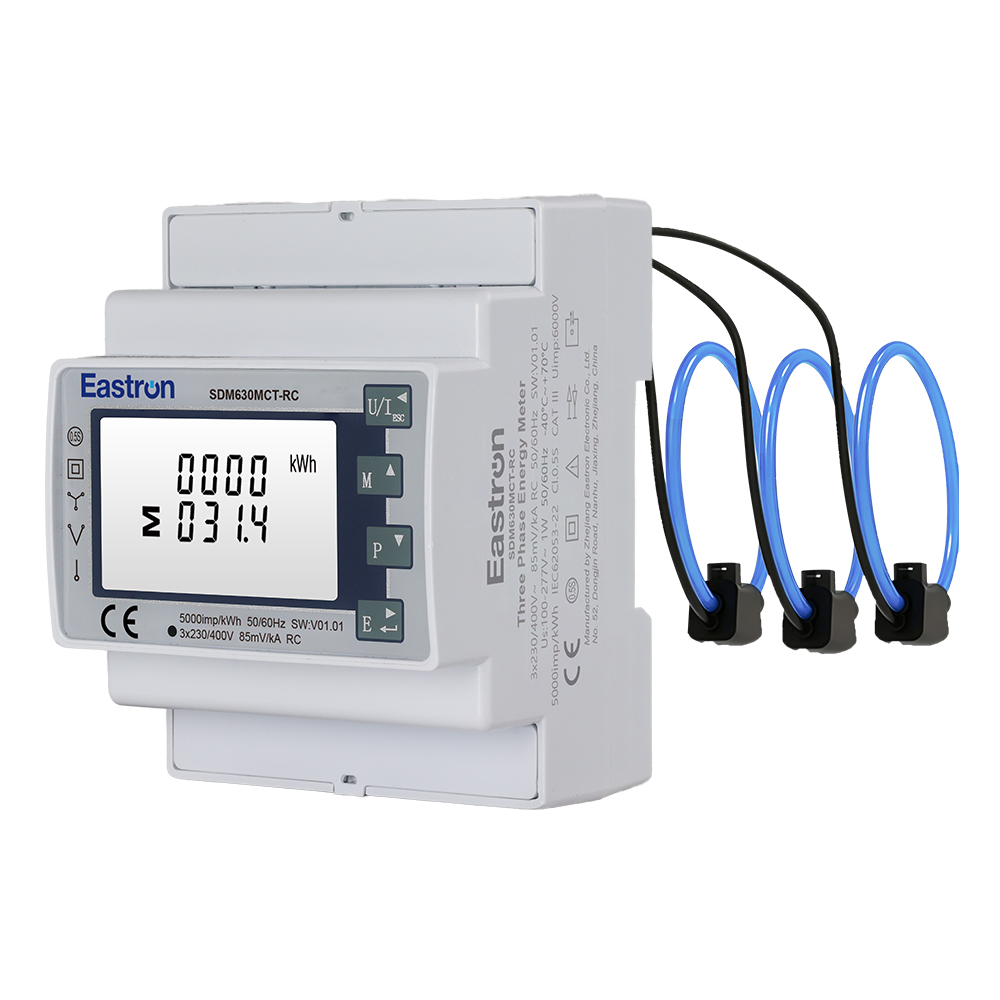
A representative example of the DIN-rail CT-operated format is the SDM630MCT family, which accepts 1 A or 5 A CTs and covers the standard three-phase wiring configurations.
 Eastron SEM3-M CT-Operated Three-Phase Modbus Energy MeterDIN-rail meter for 3P4W, 3P3W, or 1P2W systems, with three included CTs and multi-parameter measurement via RS485 Modbus RTU.View Product →
CTs deserve as much attention as the meter. Solid-core transformers are compact and precise, but the conductor has to be disconnected to fit them, which rules them out for retrofits. Split-core CTs open and clamp around an existing cable, making them the practical default for installed panels and for projects where downtime is unacceptable.
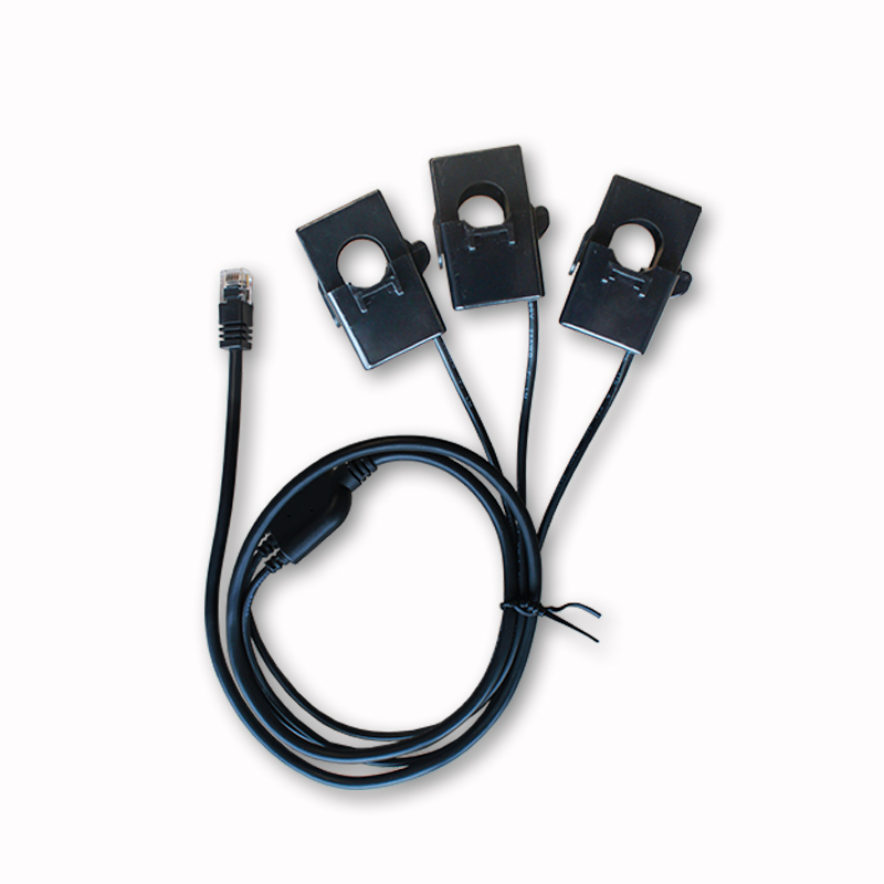
Three-phase installations often use a three-in-one CT block that wraps all three phases in a single housing. It saves space, keeps phase spacing consistent and reduces the chance of mixing up CTs during installation. Output is typically 5 A or 1 A, and versions with RJ12 terminals make the secondary connection almost plug-and-play.
Where conductors are large, irregular or already fixed in place, flexible Rogowski coils are the alternative: no magnetic core to saturate, light to handle, and able to wrap around busbars that no clamp-type CT would fit. They need an integrator to convert the output into a signal the meter can use.
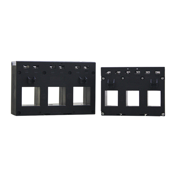 Eastron ESCT-C Series Three-Phase 3-in-1 Current TransformerDIN-rail 3-in-1 CT for cable or busbar installation, 60 A to 630 A primary and 1 A or 5 A secondary.View Product →
Most three-phase CT metering faults are not meter faults at all. They come from installation details that are easy to get wrong and tedious to diagnose afterwards.
If energy data is used for billing or regulated settlement, approvals matter more than any single specification. In Europe, MID approval is the usual baseline for billing applications. In North America, UL or ETL listing is what inspectors and utilities expect. In Germany, charging infrastructure adds PTB and Eichrecht requirements for AC and DC charging points.
These approvals are specific to a model and often to a variant of that model, so it is worth checking the certificate rather than the family name. A CT-operated three-phase MID meter, for instance, is a different article from the equivalent UL-listed unit even when the measurement engine behind it is similar.
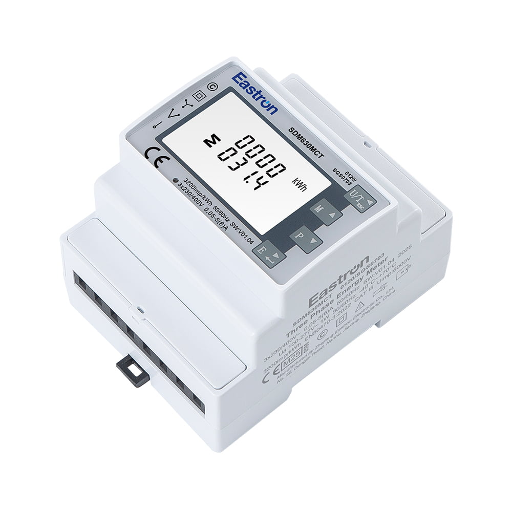 Eastron SDM630MCT CT-Operated Three-Phase MID Energy MeterDIN-rail CT/PT-operated meter for 3P4W, 3P3W, and 1P2W systems, with RS485 Modbus, pulse outputs, and MID certification.View Product →
Only if the currents are summed outside the meter, because a standard three-phase CT meter measures one circuit. Multi-circuit versions that combine several three-phase feeds in a single unit exist and are usually the better answer for rack or feeder-level monitoring.
Every reading is scaled by the same factor, so energy will be consistently over- or under-reported. The error is easy to miss because the numbers stay plausible, so always verify the configured ratio against the CT label.
Many are self-powered from the measured voltage, which is convenient inside a panel. Others need an auxiliary supply, particularly where communication modules or displays draw extra current, so check the datasheet before designing the wiring.
Choosing a three-phase meter with CT inputs comes down to matching three things: the load current, the CTs, and the way the data will be used. Get those right and the installation tends to stay quiet for years.
Eastron Electronic manufactures energy meters, current sensors, Rogowski coils and communication gateways from its base in Jiaxing, China, with research and development teams in China and the United Kingdom. You can read more about the company and its product lines on our about page, and datasheets, user manuals and protocol documents for the SDM630MCT range and other series are collected in the download area.
Your email address will not be published. Required fields are marked *

We develop and produce high performance electricity meters, power analyzers, current sensors, communication modules and management systems.
Address:NO. 52, Dongjin Road, Nanhu, Jiaxing, Zhejiang, China
Copyright @ Eastron Electronic Co., Ltd. All rights reserved
