
 English
 Español
 Deutsch
 中文简体
中文简体
Product Consultation
Your email address will not be published. Required fields are marked *
Content
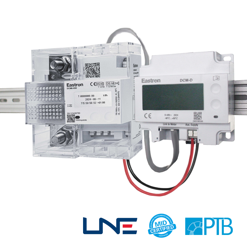
A DC energy meter is an electronic instrument designed to measure and record the flow of direct current electrical energy in a circuit over time. Unlike AC energy meters — which measure the sinusoidal alternating current supplied by utility grids — DC energy meters are built specifically for systems where current flows in a single, fixed direction. These include solar photovoltaic arrays, battery storage systems, electric vehicle charging infrastructure, telecommunications power supplies, industrial DC bus systems, and off-grid power installations. As the global energy landscape shifts toward distributed renewable generation and electrified transportation, accurate DC energy measurement has become a critical requirement in a growing range of residential, commercial, and industrial applications.
The fundamental role of a DC energy meter is to calculate the product of voltage and current over time — expressed in watt-hours (Wh) or kilowatt-hours (kWh) — and present that data in a format useful for billing, performance monitoring, system diagnostics, or regulatory compliance. While the underlying measurement principle is straightforward, the practical challenges of accurate DC measurement — including bidirectional current flow in battery systems, wide voltage ranges in solar applications, and the need for isolation in high-voltage DC circuits — make meter selection a technically demanding task that directly affects the reliability and financial integrity of an energy system.
DC energy meters use two fundamental measurements — voltage and current — to calculate power and, by integrating power over time, cumulative energy consumption or generation. Voltage measurement is typically performed directly across the circuit terminals using a high-impedance voltage divider inside the meter, which scales the measured voltage down to a level safe for the internal analog-to-digital converter. Current measurement is more technically complex and is handled through one of several methods depending on the application's current range, accuracy requirements, and circuit isolation needs.
The most common current sensing method in DC energy meters is the shunt resistor — a precision low-resistance element inserted in series with the circuit being measured. The voltage drop across the shunt is proportional to the current flowing through it, and the meter's internal circuitry amplifies and digitizes this small voltage to derive the current value. Shunt-based meters are highly accurate, cost-effective, and capable of measuring bidirectional current flow, making them well suited for battery charge and discharge monitoring. Their limitation is that the shunt must be electrically in series with the circuit, which means the meter shares the same ground reference as the measured circuit and introduces a small but measurable power loss — typically less than 0.1% of measured current at rated load.
Hall effect sensors measure the magnetic field generated by current flowing through a conductor, converting that field strength into a proportional voltage signal without any direct electrical contact with the measured circuit. This galvanic isolation makes Hall effect-based DC meters ideal for high-voltage DC applications — such as EV battery management systems or utility-scale solar inverter monitoring — where direct connection between the measurement circuit and the signal processing electronics would create safety hazards or require expensive isolation components. Hall effect sensors also support higher current ranges (up to thousands of amperes) with lower physical insertion loss than equivalent shunt resistors, though they typically offer slightly lower accuracy than precision shunts at low current levels.
Choosing the wrong DC energy meter for an application results in inaccurate data, potential safety issues, or premature equipment failure. The following specifications should be carefully evaluated against your system's actual operating conditions before finalizing a meter selection.
| Specification | What It Defines | Typical Range |
| Voltage Range | Maximum and minimum DC voltage the meter can safely measure | 9V – 1,500V DC |
| Current Range | Maximum continuous current the meter or shunt can handle | 10A – 10,000A |
| Accuracy Class | Maximum percentage error at full-scale measurement | Class 0.2 to Class 2.0 |
| Bidirectional Measurement | Ability to measure both import and export energy separately | Required for battery and grid-tied systems |
| Communication Protocol | Interface for data output to monitoring systems | RS485/Modbus, CAN, pulse, M-Bus, Ethernet |
| Operating Temperature | Ambient temperature range for specified accuracy | -25°C to +70°C |
| Display Type | Local readout format | LCD, LED, or no display (data output only) |
Accuracy class deserves particular attention in applications where energy data is used for financial settlements, regulatory reporting, or performance guarantees. A Class 0.5 meter introduces a maximum measurement error of 0.5% at full scale — acceptable for most commercial energy monitoring applications. Class 0.2 meters are specified in revenue-grade metering applications, such as EV charging stations subject to legal metrology requirements or utility-scale solar plant performance contracts where even fractional percentage measurement errors translate to significant financial discrepancies over a year of operation. For general system monitoring and diagnostics, Class 1.0 or Class 2.0 meters are often sufficient and considerably less expensive.
DC energy meters serve a diverse range of industries and system types, each with distinct requirements that influence meter design, accuracy class, communication interface, and installation method. Understanding how DC meters are used in each major application area helps clarify the trade-offs involved in meter selection.
In solar photovoltaic installations, DC energy meters are placed between the solar array and the inverter to measure the raw DC energy generated by the panels before conversion to AC. This measurement provides a direct indicator of panel performance, independent of inverter efficiency variations, and is essential for diagnosing whether underperformance originates in the PV array itself or in the inverter. String-level DC meters — one per string of panels — allow granular performance comparison between strings, enabling rapid identification of shading, soiling, or degradation issues affecting individual strings without requiring more expensive module-level monitoring hardware. For utility-scale solar plants, revenue-grade Class 0.2 DC meters are installed at the array combiner box level to provide bankable energy yield data for performance ratio calculations and investor reporting.
Battery storage applications place the most demanding requirements on DC energy meters because current flows bidirectionally — into the battery during charging and out during discharge. A DC meter used in battery monitoring must accurately measure both directions independently and maintain accuracy across a wide dynamic range, from the trickle currents present during float charging to the high pulse currents drawn during rapid discharge cycles. State-of-charge estimation algorithms in battery management systems (BMS) rely on precise coulomb counting — the continuous integration of current over time — which requires a meter with very low offset error and fast sampling rates to avoid accumulating significant charge tracking errors over extended charge-discharge cycles.
DC fast charging stations for electric vehicles require energy meters that meet legal metrology standards, since the metered energy data is the basis for billing the vehicle owner. In many jurisdictions, DC meters used in EV charging must be certified to MID (Measuring Instruments Directive) standards in Europe or NTEP (National Type Evaluation Program) standards in North America, ensuring that measurement accuracy is independently verified and legally defensible. These meters must also operate accurately across the wide voltage range of modern DC fast chargers — from 200V for older CHAdeMO-compatible vehicles up to 920V or higher for high-power CCS charging — while maintaining accuracy at both low and high current levels as the charging session progresses and the battery nears full capacity.
Modern DC energy meters are rarely standalone instruments — they are nodes in larger energy management and monitoring systems that aggregate data from multiple meters, inverters, and sensors to provide a comprehensive picture of energy flows across a facility or installation. The communication protocol supported by a DC meter determines how easily it integrates with existing infrastructure and what level of data resolution and real-time visibility is achievable.

Even a high-accuracy DC energy meter will deliver poor results if it is incorrectly installed. Several practical installation factors have a direct impact on measurement accuracy and long-term meter reliability that must be addressed during system design and commissioning.
Shunt resistor placement is critical — the shunt must be installed in a location where the full circuit current passes through it without any parallel paths that would cause a portion of the current to bypass the measurement element. In systems with multiple parallel battery strings or solar array combiner boxes, a separate shunt must be installed in each parallel branch if individual branch monitoring is required, rather than placing a single shunt on the combined output bus. The shunt's connection cables must be kept as short as possible and routed away from high-current conductors that could induce electromagnetic interference into the millivolt-level voltage signal being measured across the shunt.
Thermal management of the shunt is another frequently overlooked installation requirement. Shunt resistors have a defined temperature coefficient — their resistance changes slightly with temperature — which introduces measurement error if the shunt operates significantly above or below its calibration temperature. High-current shunts must be adequately ventilated and not enclosed in sealed junction boxes where heat buildup would be trapped. Some precision shunt-based meters include temperature compensation circuitry that corrects for shunt resistance drift, but this compensation is only effective within the meter's specified operating temperature range.
DC energy meters, like all precision measurement instruments, are subject to calibration drift over time — particularly after exposure to sustained high currents, thermal cycling, or transient overvoltage events from switching operations or lightning-induced surges. Establishing a periodic calibration verification schedule is essential in applications where the metered data supports financial transactions, performance guarantees, or regulatory reporting.
For revenue-grade applications, recalibration intervals of one to three years are typical, with verification performed using a calibrated reference standard traceable to national metrology institute standards. In less critical monitoring applications, annual visual inspection combined with a simple cross-check against another known-accurate meter at a reference load point provides a practical confidence check that does not require laboratory-grade test equipment. Firmware updates from the meter manufacturer should also be applied periodically, as these often include corrections for known measurement anomalies or improvements to the meter's performance at low load conditions — a region where many DC energy meters exhibit higher relative measurement errors than at rated current.
Your email address will not be published. Required fields are marked *
We develop and produce high performance electricity meters, power analyzers, current sensors, communication modules and management systems. China Custom Smart Meters Manufacturers and Factory
Address:NO 52, Dongjin Road, Nanhu, Jiaxing, Zhejiang, China
Copyright @ Eastron Electronic Co., Ltd. All rights reserved Electricity Meters Manufacturers
