
 English
 Español
 Deutsch
 中文简体
中文简体

Product Consultation
Your email address will not be published. Required fields are marked *
Content
A DC energy meter measures the voltage and current flowing through a direct current circuit and calculates power consumption or generation over time, typically displaying the result in watt-hours or kilowatt-hours. Unlike AC energy meters, which must account for phase angle and reactive power in their calculations, DC meters work with a more straightforward relationship between voltage and current, since DC circuits do not have a phase difference between the two values. This makes the underlying measurement simpler in principle, though achieving accurate readings still depends heavily on the quality of the current sensing method used inside the meter.
DC energy meters have become increasingly important as solar power systems, battery storage installations, and electric vehicle charging infrastructure have expanded, since all of these systems generate or consume power in DC form before any conversion to AC takes place. Accurately tracking DC-side energy flow allows system owners to monitor solar panel output before inverter losses, measure battery charge and discharge cycles precisely, and verify EV charging session totals for billing purposes.
The method a DC energy meter uses to sense current has a direct impact on its accuracy, installation complexity, and suitability for different current ranges. The two most common approaches are shunt resistor sensing and Hall effect current transducers.
A shunt-based meter measures current by detecting the small voltage drop that occurs across a precision resistor, called a shunt, installed directly in series with the circuit being monitored. This method offers excellent accuracy, often within 0.5 percent or better, and tends to be more affordable than Hall effect alternatives at similar current ratings. The tradeoff is that the shunt must be wired directly into the circuit, requiring the system to be de-energized during installation, and the shunt itself introduces a small amount of resistance and associated power loss into the circuit, which becomes more significant at very high current levels.
Hall effect sensors measure current by detecting the magnetic field generated around a conductor without requiring direct electrical contact with the circuit, which allows for non-invasive installation using a clamp-style sensor around an existing cable. This makes Hall effect meters considerably easier to retrofit onto existing systems without interrupting power, and they introduce no additional resistance into the circuit since there is no physical break in the conductor. Accuracy is generally slightly lower than premium shunt-based designs, and Hall effect sensors can be more susceptible to interference from nearby magnetic fields if not properly shielded or positioned.
DC energy meters serve a wide range of industries where direct current power flow needs to be tracked accurately for performance monitoring, billing, or system diagnostics. The following applications represent the most common use cases driving demand for these meters.
DC energy meters are typically rated with an accuracy class that indicates the maximum allowable error in their measurements under specified conditions. A meter rated at Class 0.5 will have a measurement error within plus or minus 0.5 percent of the true value, while a Class 1.0 meter allows for a larger error margin of up to 1 percent. The required accuracy class depends heavily on the application, since billing-grade applications like EV charging stations or utility-connected systems generally require stricter accuracy than internal monitoring applications used purely for performance tracking.
| Accuracy Class | Maximum Error | Typical Use Case |
| Class 0.2 | 0.2% | Revenue-grade billing and regulatory compliance |
| Class 0.5 | 0.5% | EV charging and solar performance verification |
| Class 1.0 | 1.0% | General system monitoring and diagnostics |
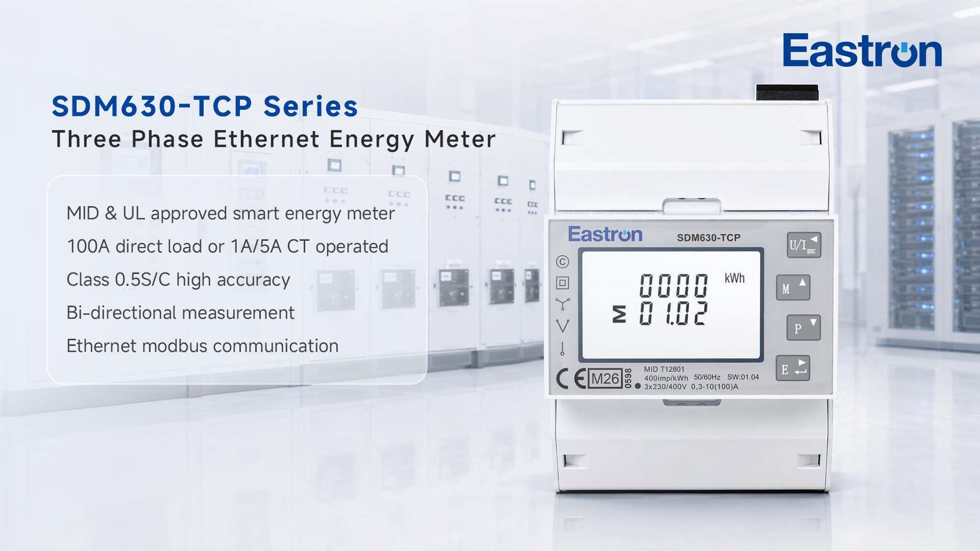
Most modern DC energy meters include a digital communication interface that allows data to be transmitted to a central monitoring system, building management platform, or cloud-based dashboard rather than requiring manual readings from a local display. Modbus RTU over RS-485 remains one of the most widely supported protocols in industrial and solar applications due to its reliability over longer cable runs and broad compatibility with existing programmable logic controllers and data loggers. Modbus TCP, which runs over standard Ethernet networks, is increasingly common in newer installations where the meter needs to integrate directly into a facility's existing IT network infrastructure.
Some meters also support CAN bus communication, which is particularly common in EV charging and battery management applications due to its widespread use in automotive and battery electronics. When selecting a meter, confirming protocol compatibility with the existing monitoring or control system in advance avoids costly integration delays after the meter has already been installed.
Selecting a DC energy meter requires matching its voltage and current measurement range to the actual operating conditions of the circuit being monitored, with some margin above the expected maximum values to accommodate occasional surges or future system expansion. A meter rated too close to its maximum operating range may show reduced accuracy near the upper end of its scale, while a meter rated far beyond the actual circuit conditions may lose precision at the lower end of its measurement range, since most sensors are optimized for accuracy within a specific portion of their rated capacity.
For solar applications specifically, it is worth checking the meter's rated voltage against the maximum open-circuit voltage the array could reach in cold weather conditions, since panel voltage rises as temperature drops, and this peak condition should fall safely within the meter's rated input range rather than just its typical operating voltage.
Proper installation begins with confirming polarity is correctly observed at both the voltage sensing and current sensing connections, since reversed polarity on a DC meter typically results in either a negative reading or, in some designs, a complete failure to register power flow at all. For shunt-based meters, the sense wires connecting to the shunt should use the smallest practical gauge recommended by the manufacturer, since these wires only carry a tiny measurement signal and oversized wiring can sometimes introduce unwanted voltage drop into the reading.
Hall effect clamp sensors should be installed with the conductor centered properly within the sensing aperture, since off-center placement can introduce measurement error in some sensor designs. It is also good practice to verify meter readings against a calibrated reference instrument shortly after installation, confirming the system is reporting accurately before relying on its data for billing, performance analysis, or warranty claims.
Your email address will not be published. Required fields are marked *
We develop and produce high performance electricity meters, power analyzers, current sensors, communication modules and management systems. China Custom Smart Meters Manufacturers and Factory
Address:NO 52, Dongjin Road, Nanhu, Jiaxing, Zhejiang, China
Copyright @ Eastron Electronic Co., Ltd. All rights reserved Electricity Meters Manufacturers
