
 English
 Español
 Deutsch
 中文简体
中文简体

Product Consultation
Your email address will not be published. Required fields are marked *
Content
Selecting the right current transformer (CT) is a critical step in designing reliable electrical measurement and protection systems. A properly specified CT delivers accurate metering, reliable protection relay operation, and safe, predictable behavior under fault conditions. Mistakes in ratio selection, burden estimation, or class selection lead to measurement errors, relay mis-operations, overheating, or even hazardous secondary circuit voltages. This article provides a practical, step-by-step approach to selecting CTs for measurement and protection applications.
Start by clarifying whether the CT is for metering (billing, energy monitoring, precise measurement) or for protection (relay tripping, fault detection). Metering CTs prioritize accuracy across a narrow range around rated current, while protection CTs must remain linear and not saturate under high fault currents so relays see true fault magnitudes. Many installations require both functions; in such cases specify separate CTs or combined CTs with clearly defined performance across both operating ranges.
Metering CTs typically use accuracy classes (e.g., 0.1, 0.2, 0.5) that define permissible error at or near rated current. Protection CTs are specified by characteristics such as knee-point voltage and accuracy under composite errors (e.g., accuracy limit factor), ensuring reliable relay input during faults. Match the CT type to the priority function, and if one CT must serve both, ensure its specifications explicitly cover both measurement and high fault performance.
Identify the maximum continuous primary current the CT will see and the maximum short-circuit (fault) current that could flow in the circuit. Choose a CT primary rated for the continuous operating current and ensure the CT’s thermal rating can handle the expected heating. For protection CTs, the expected fault current informs the knee-point and saturation requirement so relay accuracy is preserved during high-current events.
Use load studies, single-line diagrams, and upstream source impedance calculations to establish continuous and prospective short-circuit currents. If anything is uncertain, err on the side of higher short-circuit capability when specifying protection CTs to avoid unexpected saturation.
CT ratio selection (primary : secondary) should reflect the measurement system and relay settings. Common secondary ratings are 1 A or 5 A; choose the secondary current standard used by your metering and protection equipment. Pick a primary:secondary ratio that places nominal operating points near the CT’s rated performance for accuracy and minimizes burden-related errors.
Accuracy class indicates permissible error for metering CTs; common classes include 0.1, 0.2, and 0.5. For protection CTs, accuracy is expressed in terms of accuracy limits and composite error under high currents. Burden refers to the total impedance (expressed in VA) presented by connected meters, relays, and cabling on the CT secondary. A CT must be able to drive its specified accuracy at the anticipated burden.
Sum the VA ratings of all secondary devices and add VA for the cable run (calculate using cable resistance and nominal secondary current). Specify a CT with a rated burden higher than this sum; where margin is tight, select a CT with a lower specified error at the expected burden.
For protection CTs, knee-point voltage (Vk) describes when the CT core begins to saturate; a higher knee point delays saturation and improves behavior during fault transients. Saturation leads to distorted secondary current and can compromise relay performance. Specify knee-point and saturation limits suited to the maximum fault current and relay requirements.
Use a CT with a defined high knee point when protection is time-critical or when relays require accurate waveform reproduction during high current transients. Many modern protection schemes require CTs that meet defined Vk and accuracy limit factors—confirm relay manufacturer guidance when in doubt.
Verify the CT’s thermal continuous current rating and short-time thermal withstand. CTs must not overheat under sustained currents nor be damaged during short-duration fault currents. Also confirm the required insulation level—rated system voltage, system grounding arrangement, and physical clearances affect insulation class and mounting choice.
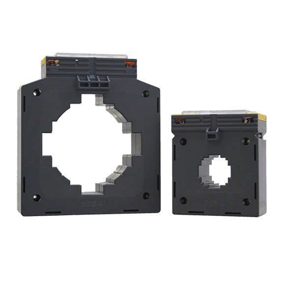
Choose among wound primary, toroidal, bar-type, and split-core (split) CTs according to installation constraints. Wound and bar-type CTs are common in switchgear and panels; split-core CTs provide retrofit convenience but often have lower accuracy or burden ratings. Confirm that the chosen form factor fits panel cutouts, busbar dimensions, and service access requirements.
| CT Type | Typical Use | Notes |
| Wound/core-and-coil | High-accuracy metering, protection | Good accuracy, robust thermal ratings |
| Toroidal (solid core) | Panel and switchgear installations | High stability and accuracy |
| Bar-type (primary conductor as core) | Busbar and high-current feeders | Simple construction, robust |
| Split-core | Retrofits and temporary monitoring | Easy install, may trade accuracy |
Always treat the CT secondary as a low-impedance source: never leave CT secondaries open-circuited under load, as this can generate dangerously high voltages and damage the CT. Design wiring routes with the shortest practical secondary runs and twisted pairs for metering circuits to minimize induced noise. Ensure protective grounding or equipotential bonding follows applicable electrical practices for the installation.
Terminate secondaries into the measuring device or a shorting terminal block during commissioning. Use insulated, appropriately rated conductors sized to limit voltage drop. Provide labeled shorting links in the panel for safe maintenance procedures.
Before final commissioning, perform ratio verification, polarity checks, and secondary burden checks. For protection CTs, test knee-point and saturation behavior where practical, and confirm relay pickup and time-current characteristics with expected CT performance. Keep records of factory test certificates and on-site validation tests for future troubleshooting and maintenance.
Use the checklist below to ensure no critical parameter is overlooked when specifying CTs.
| Item | What to confirm |
| Application | Metering, protection, or both |
| Primary rating | Continuous primary current rating |
| Secondary rating | 1 A or 5 A as required |
| Accuracy / class | Metering class or protection accuracy limits |
| Burden | Calculated VA including cable and devices |
| Knee-point / saturation | Protection CT requirement verified |
| Thermal ratings | Continuous and short-time withstand |
| Mounting & form factor | Panel, busbar, or retrofit constraints |
Choosing the right CT requires balancing measurement accuracy, protection performance, thermal capability, and installation realities. Follow a methodical process: define the application, capture primary and fault levels, estimate burden, choose ratio and secondary current, and verify knee point and thermal ratings for protection CTs. Proper wiring, testing, and documentation complete a robust specification so the CT performs safely and reliably across the system lifecycle.
Your email address will not be published. Required fields are marked *
We develop and produce high performance electricity meters, power analyzers, current sensors, communication modules and management systems. China Custom Smart Meters Manufacturers and Factory
Address:NO 52, Dongjin Road, Nanhu, Jiaxing, Zhejiang, China
Copyright @ Eastron Electronic Co., Ltd. All rights reserved Electricity Meters Manufacturers
