
 English
 Español
 Deutsch
 中文简体
中文简体

Current transformers (CTs) are the primary sensing interfaces between high-current power circuits and the low-voltage protection and metering equipment used in substations and transmission networks. This article focuses on practical deployment: how CTs feed protective relays, how to select and size CTs for different protection schemes, common installation and testing practices, and how modern sensor technologies change protection design. The objective is to give concrete, actionable guidance engineers and technicians can apply when designing, commissioning, or maintaining protection systems.
Content
- 1 CTs as the primary interface for protective relays
- 2 Differential protection: CT matching, polarity and vector compensation
- 3 Overcurrent, directional and distance protection: CT performance needs
- 4 Busbar and feeder protection: summation and redundancy
- 5 CT selection, knee-point, burden and accuracy classes
- 6 Installation, commissioning and maintenance practices
- 7 Table: Typical CT specification pairs for common protection uses
- 8 Digital and optical CTs: practical benefits and migration notes
- 9 Practical checklist for commissioning CT-protection systems
CTs as the primary interface for protective relays
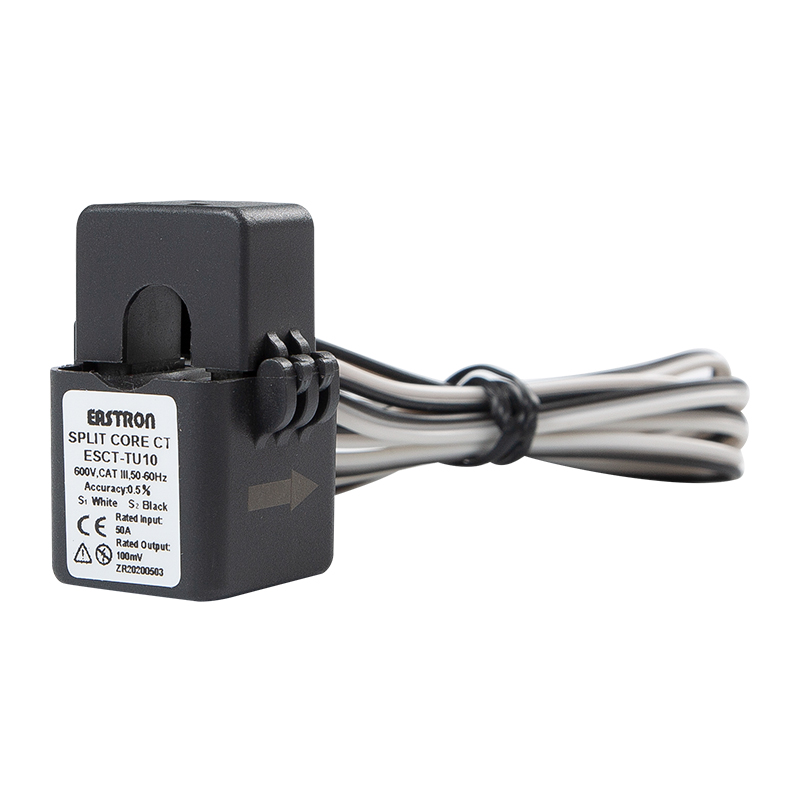
A CT converts large primary currents to standardized secondary currents (commonly 1 A or 5 A) while providing galvanic isolation. Protective relays—overcurrent, differential, directional and distance relays—depend on the CT secondary to represent the primary fault waveform with minimal distortion, correct polarity, and within specified ratio and phase error limits. Practical implications: choose CTs with suitable dynamic range so the relay sees both load-level currents and high-magnitude fault currents without severe saturation.
Differential protection: CT matching, polarity and vector compensation
Differential schemes compare currents entering and leaving a protected zone. For dependable operation:
- Install CTs with identical accuracy class and ratio on each end of the protected element or apply ratio correction in the relay configuration.
- Verify CT polarity markings and wiring — incorrect polarity is the single most frequent cause of false differential trips.
- Account for transformer vector groups and phase shifts by using CT connections or relay settings that compensate for expected phase displacement.
- Use restraint, slope, or harmonic-blocking features in relays to avoid tripping on inrush magnetizing currents; these features still assume correctly performing CTs.
Overcurrent, directional and distance protection: CT performance needs
Overcurrent relays act on magnitude and time characteristics; directional and distance relays require accurate phase relationships between current and voltage. Practical points:
- For overcurrent protection, select CTs that remain linear at expected fault levels to avoid under-reading that delays tripping.
- Directional relays rely on phase-angle information; choose CTs with low phase displacement across the operating range.
- For distance protection, CT errors translate directly into impedance calculation errors—use CTs with verified accuracy class and check relay CT compensation settings.
Busbar and feeder protection: summation and redundancy
Bus protection usually sums secondary currents from all feeders; any non-zero algebraic sum indicates an internal bus fault. Implementation guidance:
- Maintain consistent CT ratios across feeders feeding the same summation scheme, or include ratio compensation in the summation circuit.
- Use redundant CTs or dual-core CTs where high availability is required; perform secondary circuit monitoring to detect wiring or shorting failures.
CT selection, knee-point, burden and accuracy classes
Selection must match application priorities—metering vs protection. Key parameters and practical checks:
- Accuracy class: use 0.2/0.5 class for metering, and protection classes (e.g., 5P/10P) or specially specified protection CTs for relaying.
- Knee-point voltage and saturation: ensure the CT’s knee-point exceeds the maximum secondary voltage expected under fault plus connected burden.
- Burden calculation: sum cable impedance, relay input impedance and any auxiliary devices; confirm CT rating keeps secondary current within accuracy limits under that burden.
- Thermal and mechanical ratings: verify continuous thermal rating for conductor size and short-time thermal withstand for fault clearing durations.
Installation, commissioning and maintenance practices
Follow strict procedures to prevent CT-related protection failures:
- Never open a CT secondary while primary is energized—always short or load the secondary during maintenance and testing.
- Perform secondary injection tests to validate relay pickup and operate points, and perform primary injection where accessible to confirm end-to-end behavior.
- Document CT ratio, polarity, burden and serial numbers; include these details in protection coordination studies and relay settings logs.
- Periodically inspect insulation, tightness of connections, and perform ratio/phase-error tests as part of preventive maintenance.
Table: Typical CT specification pairs for common protection uses
| Application | Accuracy Class | Typical Ratio | Key Considerations |
| Metering | 0.2 / 0.5 | 1000:1, 600:1 | High linearity at load currents, low phase error |
| Protection (Feeder / Bus) | 5P / 10P / PX | 400:1, 200:1 | High knee-point, withstand short-time thermal stress |
| Differential (Transformer / Generator) | Custom matched / 5P | Varies (must match ends) | Strict matching, correct polarity, vector compensation |
Digital and optical CTs: practical benefits and migration notes
Electronic and optical CTs provide a wide dynamic range, immunity to magnetic saturation, and direct digital outputs suitable for IEC 61850 sampling and modern IED interfaces. When migrating:
- Validate latency and synchronization (time stamps) against existing relay algorithms; distance and differential functions are sensitive to timing.
- Keep mechanical CTs in parallel for a transition period or maintain dual-redundant channels to verify behavior under fault conditions.
Practical checklist for commissioning CT-protection systems
- Confirm CT ratio and polarity tags match relay settings and wiring diagrams.
- Measure secondary burden and ensure it is within CT datasheet limits.
- Run secondary injection tests for all protective functions and record pickup and operate points.
- Perform an end-to-end primary injection test when possible to validate real-world performance.
- Keep a maintenance log for periodic ratio, polarity, and insulation tests.
Correct CT selection, careful installation, and disciplined testing are the practical foundations of dependable protection. When these steps are followed—appropriate accuracy classes, burden control, matched CT sets for differential schemes, and rigorous commissioning—relays will operate reliably to isolate faults quickly and preserve grid stability.
